Description
RAMPS CNC V3 Engraver A4988 Driver Expansion Board 3D Printer Shield For Arduino Carving Integrated Circuits 3D Printer Parts
Feature
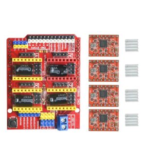
1.Uses removable A4988 or DRV8825 compatible stepper drivers.
2.The extension board can be used for carving machine,
3 d printer driver expansion board
3.GRBL 0.8 compatible. (Open source firmware that runs on an
for arduino UNO that turns G-code commands into stepper signals)
4.PWM Spindle and direction pins,4-Axis support
(X, Y, Z , A-Can duplicate X,Y,Z or do a full 4th axis with custom firmware using pins D12 and D13)
5.Compact design. Stepper Motors can be connected with 4 pin molex connectors or soldered in place.
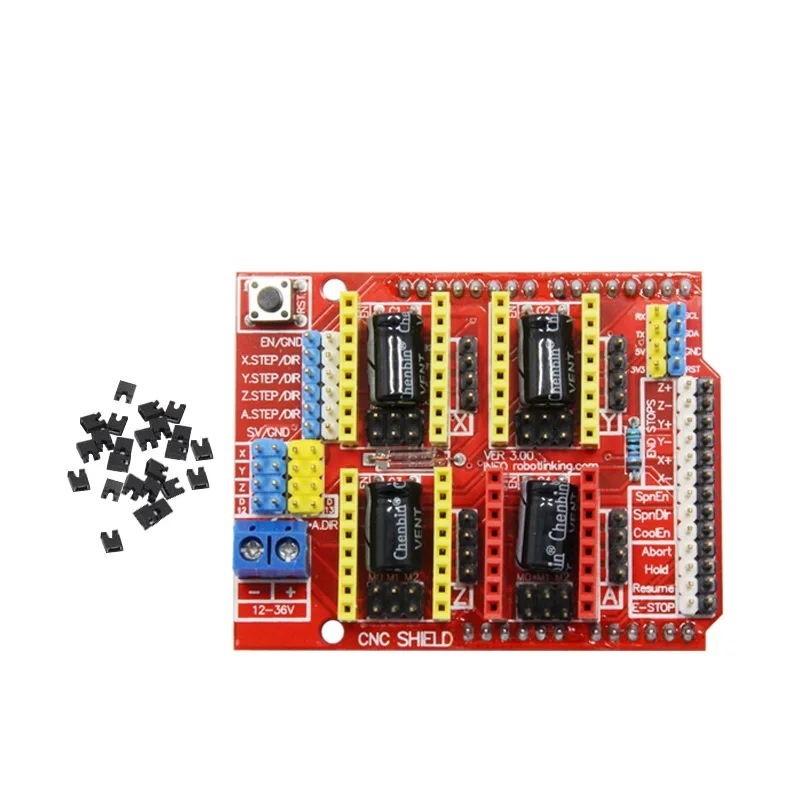
It is a total of four slots, can drive four A4988 stepper motor. Each road stepper motors only need two IO ports. In other words, six IO ports can be well managed three stepper motors. Very convenient to use.
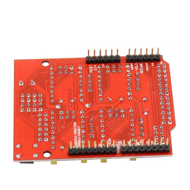
UNO for Arduino module IO port correspondence introduction.
UNO for Arduino———————- expansion board
8 ———————— EN ( stepper motor driver enable , active low )
7 ———————– Z.DIR (Z -axis direction control )
6 ———————– Y.DIR (Y -axis direction control )
5 ———————– X.DIR (X -axis direction control )
4 ———————- Z.STEP (Z -axis stepper control )
3 ———————- Y.STEP (Y -axis stepper control )
2 ———————- X.STEP (X -axis stepper control )
/ / The following is a simple stepper motor control procedures,
# define EN 8 / / stepper motor enable , active low
# define X_DIR 5 / / X -axis stepper motor direction control
# define Y_DIR 6 / / y -axis stepper motor direction control
# define Z_DIR 7 / / z axis stepper motor direction control
# define X_STP 2 / / x -axis stepper control
# define Y_STP 3 / / y -axis stepper control
# define Z_STP 4 / / z -axis stepper control
/ / Function : step . function: to control the direction of the stepper motor , the number of steps .
/ / Parameters : dir direction control , dirPin corresponding stepper motor DIR pin , stepperPin corresponding stepper motor ” step ” pin , Step number of step of no return value.
void step (boolean dir, byte dirPin, byte stepperPin, int steps)
digitalWrite (dirPin, dir);
delay (50);
for (int i = 0; i <steps; i + +)
digitalWrite (stepperPin, HIGH);
delayMicroseconds (800);
digitalWrite (stepperPin, LOW);
delayMicroseconds (800);
}
}
Void (setup) {//Will be used in the stepper motorIOPin is set to output
(pinMode X_DIR, OUTPUT); pinMode (X_STP, OUTPUT);
(pinMode Y_DIR, OUTPUT); pinMode (Y_STP, OUTPUT);
(pinMode Z_DIR, OUTPUT); pinMode (Z_STP, OUTPUT);
(pinMode EN, OUTPUT);
(digitalWrite EN, LOW);
}
Void (loop) {
(step false, X_DIR, X_STP, 200); //XShaft motor reversalOneRing,Two hundredStep for a circle
(step false, Y_DIR, Y_STP, 200); //yShaft motor reversalOneRing,Two hundredStep for a circle
(step false, Z_DIR, Z_STP, 200); //zShaft motor reversalOneRing,Two hundredStep for a circle
Delay (1000);
(step true, X_DIR, X_STP, 200); //XShaft motor ForwardOneRing,Two hundredStep for a circle
(step true, Y_DIR, Y_STP, 200); //yShaft motor ForwardOneRing,Two hundredStep for a circle
(step true, Z_DIR, Z_STP, 200); //zShaft motor ForwardOneRing,Two hundredStep for a circle
Delay (1000);
}
Experimental phenomena: a turn of the stepper motor, pauseOneSecond, then a story circle, so the cycle.
It is worth noting that in theA4988When the module is not plugged in, step motor connection mode is:
2A, 2BFor a group (red, green),1A, 1BFor a group (blue, yellow) would like to change direction, change the location of one group can be, for example2A,and2BExchange.
Description Product
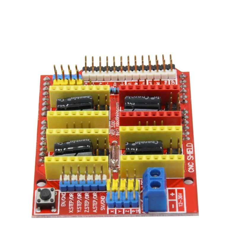
CNC Shield Board:
Latest CNC Shield Version 3
0.9 compatible. GRBL (open source firmware that runs on an uno that turns the G-code commands into stepper 37signals)
PWM Spindle and direction pins
4-Axis support (X, Y, Z, A-Can duplicate X, Y Z, or do a full 4th axis with custom firmware using pins D12 and D13)
2 x End stops for each axis (6 in total)
Coolant enable
Uses removable A4988 or DRV8825 compatible stepper drivers
Jumpers to set the Micro-Stepping for the stepper. (some drivers like the DRV8825 can do up to 1 / 32 micro-stepping)
Compact design.
Stepper Motors can be connected with pin Molex connectors or soldered 4 in place.
Runs on 12-36v DC. (at the moment only the DRV8825 drivers can handle up to 36V so please consider the operation voltage when powering the.)


Reviews
There are no reviews yet.