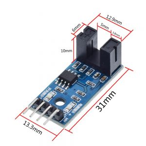
Description
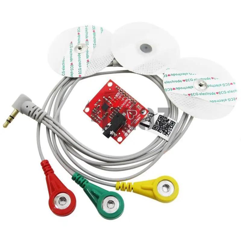
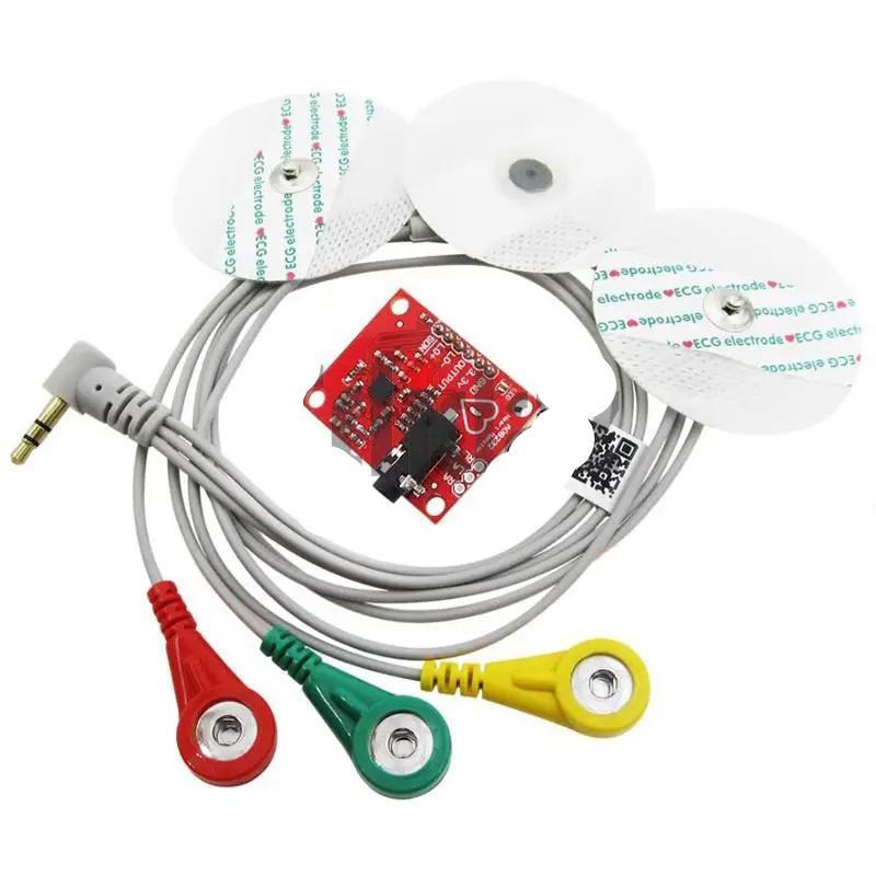
AD8232 Analog Heart Rate Pulse Sensor (ECG) – Measurement Pulse Heart ECG Monitoring Sensor Module Kit for Arduino


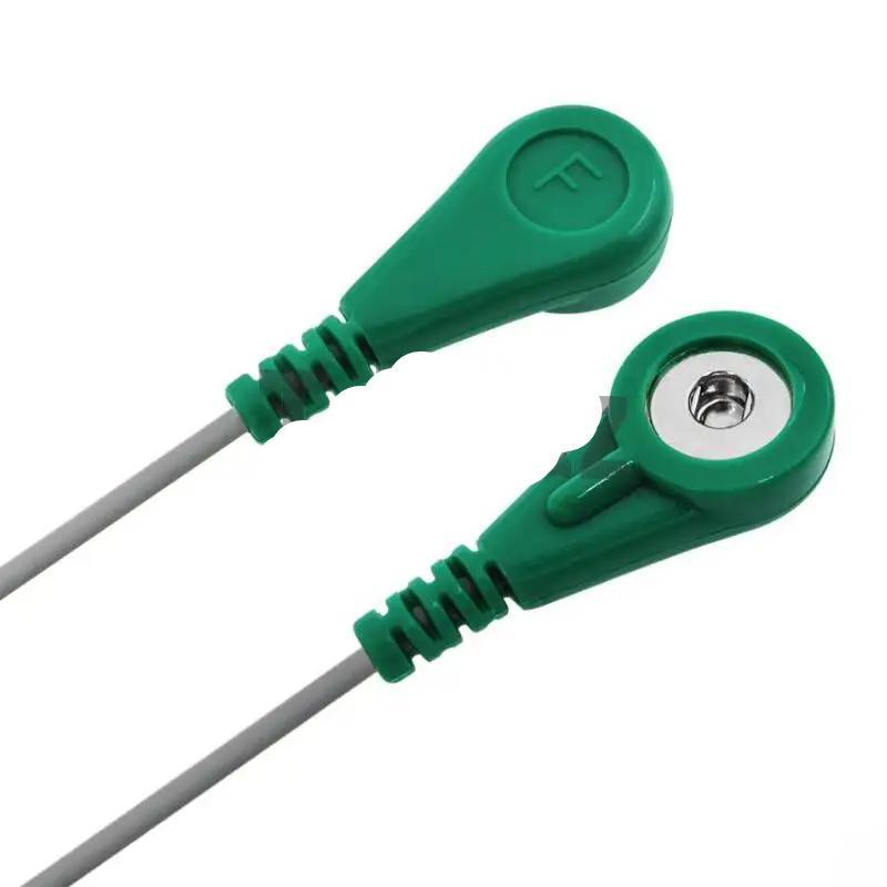
Single wire AD8232 bipolar pulse heart rate monitor ECG sensor module kit
AD8232 ECG measurement module pulse heart monitor biosignal kit w/cable
Product specifications:
-AD8232 uses a dual high-pass filter to eliminate motion artifacts and electrode half-cell potential
-AD8232 uses an operational amplifier, no need to use restrictions to build a three-pole low-pass filter to eliminate additional noise
-Rated temperature range: 0 ——– 70 degrees
-Operating temperature range: -40 —– 85 degrees
The AD8232 single-lead heart rate monitor is a cost-effective board for measuring the electrical activity of the heart.
This electrical activity can be plotted as an ECG or electrocardiogram and output as an analog reading.
application:
-Fitness and exercise heart rate monitoring
-Portable ECG
-Remote health monitor
-Gaming peripherals
-Bioelectric signal collection
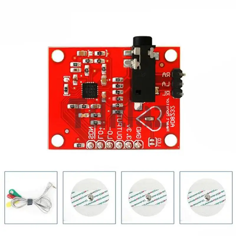
Pin number Pin name Description
1 HPDRIVE high-pass driver output. HPDRIVE should be connected to the capacitor in the first high-pass filter.
AD8232 drives this pin to keep HPSENSE at the same level as the reference voltage.
2 +IN The positive input terminal of the instrumentation amplifier. +IN is usually connected to the left arm (LA) electrode.
3 −IN The negative input terminal of the instrumentation amplifier. −IN is usually connected to the right arm (RA) electrode.
4 RLDFB Right leg drive feedback input terminal. RLDFB is the feedback pin of the right leg drive circuit.
5 RLD Right leg drive output terminal. The drive electrode (usually the right leg) should be connected to the RLD pin.
6 SW Fast recovery switch pin. This pin should be connected to the output of the second high-pass filter.
7 OPAMP+ Operational amplifier non-inverting input terminal.
8 REFOUT Reference voltage buffer output terminal. The instrumentation amplifier output is referenced to this potential.
REFOUT should be used as a virtual ground at any point in the circuit where a reference signal is needed.
9 OPAMP− The inverting input terminal of the operational amplifier.
10 OUT Operational amplifier output terminal. This output provides a fully conditioned heart rate signal.
OUT can be connected to the input terminal of the ADC.
11 LOD− The lead falls off the output of the comparator. In the DC lead-off detection mode, when the −IN electrode is disconnected,
LOD− is in a high level state, otherwise it is in a low level state. In the AC lead-off detection mode, LOD− is always in a low state.
The lead falls off the output of the comparator. In the DC lead-off detection mode, when the +IN electrode is disconnected, LOD+ is in a high level state,
Otherwise, it is in a low level state. In the AC lead-off detection mode, when the −IN or +IN electrode is disconnected, the LOD+ is at a high level.
When these two electrodes are connected, they are in a low level state.
12 LOD+
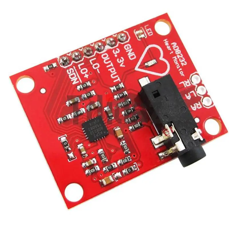
13 SDN Shutdown control input terminal. Drive SDN to a low level to enter a low-power shutdown mode.
14 AC/DC lead off mode control input terminal. For the DC lead-off mode, the AC/DC pin should be driven to a low level.
For the AC lead-off mode, the AC/DC pin should be driven to a high level.
15 FR Fast recovery control input. Driving FR to a high level enables the fast recovery mode; otherwise, it should be driven to a low level.
16 GND Power ground.
17 +VS Power supply pin.
18 REFIN Reference voltage buffer input terminal. REFIN (high impedance input pin) can be used to set the level of the reference voltage buffer.
19 IAOUT Instrumentation amplifier output pin.
20 HPSENSE High-pass detection input of instrumentation amplifier.
HPSENSE should be connected to the R and C nodes that set the corner frequency of the DC blocking circuit.
EP Exposed Pad. The exposed pad should be connected to GND or left unconnected.


Reviews
There are no reviews yet.